-
x
Description
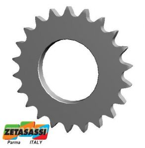
Plate wheel for torque limiters
Similar
-
1Price:from €2.20
-
2Price:from €39.20
-
3Price:from €4.10
-
4Price:from €4.30
-
5Price:from €3.20
-
6Price:from €2.80
Datasheet
Zetasassi started producing torque limiters in 1982. They are high quality, reliable safety devices.They are used to protect the controlling parts from overloads that could damage the various organs of transmission. Their use is actually essential where there is a need to ensure effective overload protection.
Under normal working conditions, they transmit the necessary torque, but slip when overloaded.Accurate adjustment of the torque is made simply by turning the adjustment ring.If the torque exceeds the set limit, the control part is automatically disconnected from the driven part.
All Zetasassi torque limiters use asbestos-free friction materials, driven by Belleville washers and regulated by a lockring that serves to regulate the torque loads.
The LF torque limiters can be supplied with or without the central crown, and can also be supplied with transmission pulleys and/or wheels not shown in the catalogue.
The LF-SL model torque limiters are equipped with a mechanical slipping device that signals when the torque to transmit exceeds the set value.In case of overload, a ball mechanism causes the movement of a ring which, in turn, can signal the overload to a limit switch or proximity sensor.After eliminating the cause of the overload and thus of the limiter slippage, it is not necessary to act on the limiter, which will simply reset the signal mechanism and automatically return the ring to its initial position immediately after the transmission resumes work.
LFG torque limiters with axial joint are supplied with a crown that is inserted in the limiter, and a pinion. The two are then coupled by a double chain.This permits axial motion transmission (two rods on the same axis) and at the same time - thanks to the torque limiter - ensures protection from overloads.
The LFG model is also available with the mechanical slip device LFG-SL
The hubs, pinions and crowns are made using C40/C45 material, and are machined directly in our workshop with our CNC machinery, with very high quality control.The rest of the materials used, such as springs, lockrings and clutch disks, are made in Italy by our established suppliers.
They can be supplied already drilled and with drive spline.
All materials: hubs, flanges, lockrings, pinions, etc., are protected by galvanization.
Note: Switches are not included
How to select the torque load and limiter and how to calibrate it:
First of all you need to establish the safety level “L”, which does not depend only on the nominal work load but also oon the inertial forces of startup and stoppage, and on the type of motor used.
Here is an example with electric motor, with standard startup and stoppage (standard means without particular overloads and without abrupt or excessively frequently startups) .L=1
We now have to decide the maximum torque Nm to consider:
(9550*L*Pkw)/G = Nm
Where:
L= Safety level (1)
Pkw = Motor power in kw (1.5kw)
G= Revolutions of transmission (1430)
(9550*1*1,5)/1430= Nm 10
So the choice of the limiter must have a load of 10 Nm or more


